PAM-XIAMEN has 4H SiC crystal for sale, which is for power electronic device and microwave power device. It has been found that there are over 250 polytypes of silicon carbide single crystal, but the most common polytypes are cubic close-packed 3C-SiC and hexagonal close-packed 4H and 6H-SiC. Among them, 4H-SiC is most widely used. These polytypes of SiC crystals have the same chemical composition, but their physical properties, especially the semiconductor characteristics such as band gap, carrier mobility, and breakdown voltage, are quite different. The main SiC crystal growth technology is PTV. The silicon carbide crystals you can buy from us are shown as following:
1. Specifications of SiC Single Crystal
Item 1
| Silicon Carbide (SiC) 4inch Crystal Specification | |||
| Grade | Production Grade | Research Grade | Dummy Grade |
| Polytype | 4H | ||
| قطر | 100.0mm ± 0.5mm | ||
| Carrier Type | N-type | ||
| المقاومة النوعية | 0.015~0.028 ohm.cm | ||
| توجيه | 4.0° ± 0.2° | ||
| Primary Flat Orientation | (10-10} ± 5.0° | ||
| Primary Flat Length | 32.5mm ± 2.0mm | ||
| Secondary Flat Orientation | Si-face: 90° cw. from primary flat ± 5° | ||
| C-face:90° cw. from primary flat ± 5° | |||
| Secondary Flat Length | 18.0mm ± 2.0 mm | ||
| Edge cracks by high intensity light | – | – | – |
| Hex Plates by high intensity light | – | – | – |
| Poly type Areas by high intensity light | – | – | – |
| MicroPipe Density | – | – | – |
| Edge chip | – | – | – |
Item 2
| Silicon Carbide (SiC)6 inch Ingot Specification | |||
| Grade | Production Grade | Research Grade | Dummy Grade |
| Poly type | 4H | ||
| قطر | 150.0mm ± 0.5mm | ||
| Carrier Type | N-type | ||
| المقاومة النوعية | 0.015~0.028 ohm.cm | ||
| توجيه | 4.0° ± 0.2° | ||
| Primary Flat Orientation | {10-10} ± 5.0° | ||
| Primary Flat Length | 47.5mm ± 2.5mm | ||
| Edge cracks by high intensity light | – | – | – |
| Hex Plates by high intensity light | – | – | – |
| Polytype Areas by high intensity light | – | – | – |
| MicroPipe Density | – | – | – |
| Edge chip | – | – | – |
2. About 4H SiC Crystal Structure
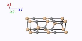
SiC crystal is a stable compound of C and Si. SiC crystal lattice structure is composed of two densely arranged sub-lattices. Each Si (or C) atom is bonded to the surrounding C (Si) atom by an oriented strong tetrahedral sp3 bond. The tetrahedral bond of SiC is very strong, but the energy of stacking fault formation is very low. This feature determines the polytype phenomenon of silicon carbide. The stacking order of the C/Si diatomic layer of each polytype is different. The silicon carbide crystal structure in 4H type displays in the following Fig.
3. Silicon Carbide Properties
The forbidden band width of SiC crystal is 2-3 times that of Si , the silicon carbide thermal conductivity is about 4.4 times that of Si, the critical breakdown electric field is about 8 times that of Si, and the saturation drift speed of electrons is twice that of Si. These properties of SiC single crystal make it the preferred material for semiconductor devices with high frequency, high power, high temperature resistance and radiation resistance.
4. Silicon Carbide Single Crystal Ingot Industry Standards
Since PAM-XIAMEN’s silicon carbide single crystal growth is strictly complied with the industry standards, and the advanced equipment and technology is used, the SiC crystal defects are low. More details about the industry criterion please refer to following parts.
4.1 Test Orientation of Monocrystalline Silicon Carbide
This standard specifies the method for determining the SiC crystal orientation using the X-ray diffraction orientation method and is applicable to the determination of crystal orientation of silicon carbide single crystals with crystal forms of 6H and 4H.
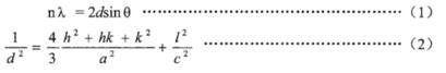
The atoms in a SiC crystal are arranged in a three-dimensional periodic manner, which can be regarded as composed of a series of parallel planes with a surface distance d. When a parallel monochromatic X-ray is incident on the plane, and the optical path difference between the X-rays on adjacent planes is n times its wavelength (n is an integer), diffraction will occur. Use a counter to detect the diffraction line, and determine the crystal orientation of the single crystal silicon carbide according to the position where it appears, as shown in Figure.

When the angle between the incident beam and the engagement plane is ѳ, the X-ray wavelength λ, the distance between crystal planes d, and the diffraction order n simultaneously satisfy Bragg’s law, the X-ray diffraction beam intensity will reach the maximum. The common SiC crystal belongs to the hexagonal crystal system, and the relationship between the interplanar spacing d and the unit cell parameters a, c and the Miller index h, K, l is shown in the formula:
4H-SiC single crystal 2ѳ angles (Cu target ka1 λ=0.15406nm)
| Diffraction surface hk1 | 2ѳ |
| (100) | 33.549° |
| (004) | 35.670° |
| (110) | 59.994° |
| (201) | 71.2333° |
| (008) | 75.760° |
| Note: (hkl) grade notation is equivalent to (hkil), j=-(k+h). | |
Under repeatable conditions, the standard deviation of the total angle deviation of the SiC crystal measured by this method is less than 0.25°.
4.2 Raman Scattcring for Determining Polytype of SiC Crystal
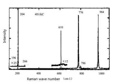
For cubic silicon carbide crystal, the different stacking methods between the Si-C diatomic layers form different crystal types. In summary, there are three categories: 3C, nH and 3nR. In these symbols, the letters C (cubic), H (hexagonal), and R (triangle) are used to indicate the lattice type of SiC crystal, and n is used to indicate the number of chemical formula units (silicon carbide) contained in the unit cell. 3C-SiC has only one Raman active mode. This vibration mode is triple degenerate and can be split into a transverse mode with a wavenumber of 796cm-1 and a longitudinal mode with a wavenumber of 972cm-1. The structures of nH-SiC and 3nR-SiC are more complicated. The larger the n, the more the number of atoms (2n) contained in the primitive cell, and the greater the number of Raman active modes. Theoretically, the number of Raman active modes of 2H-SiC, 4H-SiC, 6H-SiC and 15R-SiC are respectively 4, 10, 16, and 18. The Raman active modulus of SiC polytypes crystal structure is different, and the position where the Raman peak is generated is also different. Therefore, it is used to determine the SiC seed crystal structure.
4H-SiC Raman spectroscopy:
Raman spectroscopy data of different SiC boule crystals:
| Polytype | Crystal System | Point Group | Raman spectral line wave number cm-1 |
| 3C-SiC | Cubic | Td | 796s、972s |
| 2H-SiC | Cubic | C6v | 264w, 764w, 799w, 968w |
| 4H-SiC | Cubic | C6v | 196w, 204s, 266w, 610w, 776s, 796w, 964s |
| 6H-SiC | Cubic | C6v | 145w, 150m, 236w, 241w, 266w, 504w, 514w, 767m, 789s, 797w, 889w, 965s |
| 15R-SiC | Tripartite | C3v | 167w, 173m, 255w, 256w, 331w, 337w, 569w, 573w, 769s, 785s, 797m, 860w, 932w, 938w, 965s |
| Note: The s in the wavenumber of the Raman spectrum line means strong, m means medium, and w means weak. | |||
4.3 Measuring Single Crystal Silicon Carbide Electrical Properties By Van der Pauw
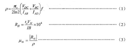
The electrical parameter test of SiC single crystal material adopts the Van der Pauw method. For a silicon carbide single crystal wafer sample of arbitrary shape and uniform thickness, four ohmic contact electrodes A, B, C, and D are made around the sample. The typical Van der Pauw sample and electrode positions are shown in Figure 1. The current and voltage of the sample are measured under zero magnetic field and magnetic field respectively, and the resistivity and Hall coefficient of silicon carbide single crystal can be calculated by formula (1) and formula (2). The sign of the Hall coefficient can be used to determine the conductivity type of the SiC ingot. Substituting resistivity and Hall coefficient into formula (3) can calculate the Hall mobility of SiC disc.
In the formula:
P – resistivity (ohm-cm);
Ru – hall coefficient (cm3/C);
uH – hall mobility (cm2/Vs);
Ts – sample thickness (cm)
VH – hall voltage (V);
VDC, VBC are the voltage measured between the DC and BC electrodes respectively;
IAB and IAD are the current passing between the AB and AD electrodes respectively;
B – magnetic flux perpendicular to the sample (T)
F – Van der Pauw correction factor
When the Hall coefficient is negative, the SiC crystal conductivity type is N-type, and when the Hall coefficient is positive, the conductivity type is P-type. Under repeatability conditions, the relative standard deviation of the measurement results of this method is less than 20%.

لمزيد من المعلومات، يرجى الاتصال بنا على البريد الإلكترونيvictorchan@powerwaywafer.com و powerwaymaterial@gmail.com.