The single crystal germanium is n type at room temperature, and the resistivity shows non-single dependence on temperature. When conduction type transits from n type to p type, the bulk germanium resistivity is in maximum, and the carrier mobility is declining. With the increasing of dopant concentration, the transition from inner to outer moves to room temperature and reflects the purity level of the crystal. Similar trend is found in high purity germanium single crystal doped with boron in different concentration. It is found that the interaction of temperature dependent and conductive principle caused by impurity band and intrinsic carrier in monocrystal germanium wafer results in the low receptor concentration (<1012/cm3). For extrinsic semiconductors, the resistance (conductivity) of the material is mainly related to the majority carrier concentration and mobility. The figure 1 shows the variation between resistivity and concentration of extrinsic germanium wafer:

Fig. 1 Non-Linear Variation of P or N Type Germanium Resistivity and Concentration
In order to improve the yield rate at home and abroad, more stringent requirements have been put forward for the radial uniformity of resistivity of single crystal. Germanium single crystals are often affected by speed and solid-liquid interface during the production process. The germanium resistivity distribution is often uneven, and the uniformity of resistivity directly affects the reliability and yield of the device. The DC linear four-probe method of measuring resistivity plays a great role in the research and production of semiconductor materials, and is one of the most extensive testing methods.
1. DC Linear Four-Point Probe for Measuring the Resistance of Germanium Wafer
The DC linear four-probe applies to the measurement of the thickness of the sample and the closest distance from the edge of the sample to the end of any probe, both of which are greater than 4 times the resistivity of the probe pitch, and the measurement diameter is greater than 10 times the probe pitch. The resistivity of a single germanium wafer is less than 4 times the probe pitch. The measuring range is 1X10⁻³ohm.cm~1X10²ohm.cm.
2. Principle for Testing Extrinsic Resistivity of Germanium
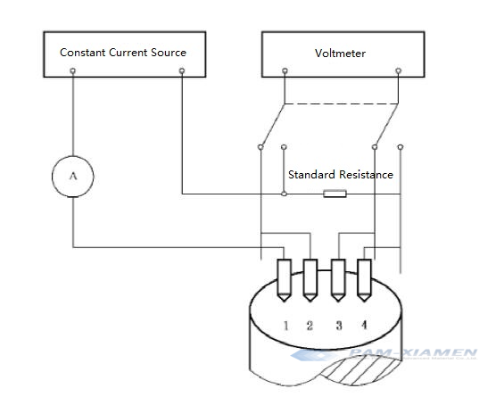
The measurement principle is shown in Figure 2. The four probes arranged in a straight line are vertically pressed on the flat surface of the semi-infinite specimen. The current I (A) between the outer probes 1 and 4, and the voltage U (V) between the inner probes 2 and 3. Under certain conditions, the resistivity p of the sample near the four probes can be calculated by formula (1) and formula (2):

“l” is probe coefficient;
“l1” is the distance between probes 1 and 2, in centimeters (cm);
“l2” is the distance between probes 2, 3, in centimeters (cm);
“l3” is the distance between probes 3 and 4, in centimeters (cm).

Fig. 2 Schematic Diagram of the Four-Probe Method
3. Equipment and Instruments for Determining Germanium Resistivity
Electromagnetic shielding room: In order to eliminate the parasitic current that the adjacent high-frequency generator may introduce in the measurement circuit, the germanium resistivity measurement must be carried out in an electromagnetic shielding room.
Constant temperature and humidity equipment: Ensure that the temperature in the resistivity test room can be stabilized within the arbitration temperature of 23±0.5°C, and the relative humidity is less than 70%.
Thermometer: Measure the surface temperature of germanium single crystal with accuracy within 0.1°C.
Four-probe resistivity tester includes:
Constant current power supply, which can provide 10-1A~10-5A DC current, its value is known and stable within ±0.5% during measurement;
Digital Voltmeter, which measures the voltage of 10-5V~1V, the error is less than ±0.5%. The input impedance of the meter should be more than three orders of magnitude greater than the resistance of the sample body plus the contact resistance between the sample and the probe;
Probe device:The probe head is made of tool steel, tungsten carbide and other materials. The diameter is about 0.5mm or 0.8mm. The indentation of the probe tip must be less than 100um. The probe spacing is measured with a measuring microscope (scale 0.01mm>. The mechanical movement rate between the probes △l/l<0.3% (△l is the maximum mechanical movement of the probe spacing, l is the probe spacing). The insulation resistance between probes is greater than 103 MΩ;
5N〜16N(総力)を提供するために必要なプローブホルダーであり、プローブとサンプルの接触位置がプローブピッチの±0.5%以内に繰り返しあることを保証できます。
4.室温でゲルマニウムの抵抗率をテストするためのステップ
ステップ1。 測定環境:サンプルは、23±0.5°Cの温度と70%以下の相対湿度のテストルームに配置されます。
ステップ2。 サンプルの準備:テストするサンプルの上面と下面をW28#エメリーで研磨して、機械的な損傷や汚れがないことを確認します。
ステップ3。 単結晶の直径に応じて、次の2つの測定位置を使用できます。
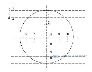
※単結晶径が100mm未満の場合の単結晶端面抵抗率の測定位置を図3に示します。

図3標準状態での純粋なゲルマニウムの抵抗率を測定するための位置、d <100mm
※単結晶径が100mm以上の場合の単結晶端面抵抗率の測定位置を図4に示します。

図4標準状態でゲルマニウム抵抗率を測定する位置、d≥100mm
ステップ4。 測定:Geサンプルが指定温度(23±0.5°C)に達したら、サンプルテーブル上で平らにカットされた単一のモデル領域でプローブを垂直に押し、電流を指定値に調整します。 電流は、1A / cm未満の弱電界条件を満たす必要があります。 ゲルマニウムロッド電流は、表1に従って選択されます。順方向および逆方向の電流方向の電圧の平均値を取ります。 サンプルの長さに応じてさまざまな式で計算します。表1を参照してください。
表1抵抗率の異なるゲルマニウム基板の電流選択
| 抵抗率範囲/(オーム* cm) | <0.01 | 0.01-1 | 1-30 | 30-100 |
| 電流/ mA | <100 | <10 | <1 | <0.1 |
| 推奨ウェーハ電流値/ mA | 100 | 2.5 | 0.25 | 0.025 |
5.ゲルマニウムの抵抗率の計算(オーム* cm)
Geウェーハの厚さはプローブピッチの4倍を超えており、単結晶セクションの抵抗率は式(1)に従って計算されます。
Calculation of single crystal radial resistivity variation:
* When the single crystal diameter is less than 100mm, the single crystal radial resistivity varies E uniformly, calculated according to formula (3).
E = [(pa – pc)/ pc] * 100%……(3)
式では:
「pa」は、エッジから6mmで測定されたゲルマニウム抵抗率の平均値(オーム* cm)を表します。
「pc」は、中央での2つの抵抗率測定値の平均値をオーム* cmで表します。
※単結晶径> 100mmの場合、ゲルマニウム単結晶の半径方向抵抗率の最大変化率Eは式(4)により算出されます。
E = [(pM – pm)/ pm] * 100%……(4)
式では:
「pM」は、測定された最大抵抗率(オーム* cm)です。
「pm」は、測定された最小抵抗率(オーム* cm)です。
サンプルがGeウェーハの場合、幾何学的補正係数Fを計算します。
サンプルの厚さWと平均プローブ距離Sの比率を計算し、線形補間を使用して、表2から補正係数F(W / S)を見つけます。
表2厚さ補正係数F(W / S)は、ゲルマニウムウェーハの厚さWとプローブ間隔Sの比率の関数です。
| W / S | F(W / S) | W / S | F(W / S) | W / S | F(W / S) | W / S | F(W / S) |
| 0.1 | 1.0027 | 0.64 | 0.9885 | 0.91 | 0.9438 | 2.8 | 0.477 |
| 0.2 | 1.0007 | 0.65 | 0.9875 | 0.92 | 0.9414 | 2.9 | 0.462 |
| 0.3 | 1.0003 | 0.G6 | 0.9865 | 0.93 | 0.9391 | 3.0 | 0.448 |
| 0.4 | 0.9993 | 0.67 | 0.9853 | 0.94 | 0.9367 | 3.1 | 0.435 |
| 0.41 | 0.9992 | 0.68 | 0.9842 | 0.95 | 0.9343 | 3.2 | 0.422 |
| 0.42 | 0.9990 | 0.69 | 0.9830 | 0.96 | 0.9318 | 3.3 | 0.411 |
| 0.43 | 0.9989 | 0.70 | 0.9818 | 0.97 | 0.9293 | 3.4 | 0.399 |
| 0.44 | 0.9987 | 0.71 | 0.9804 | 0.98 | 0.9263 | 3.5 | 0.388 |
| 0.45 | 0.9986 | 0.72 | 0.9791 | 0.99 | 0.9242 | 3.6 | 0.378 |
| 0.46 | 0.9984 | 0.73 | 0.9777 | 1.0 | 0.921 | 3.7 | 0.369 |
| 0.47 | 0.9981 | 0.74 | 0.9762 | 1.1 | 0.894 | 3.8 | 0.359 |
| 0.48 | 0.9978 | 0.75 | 0.9747 | 1.2 | 0.864 | 3.9 | 0.350 |
| 0.49 | 0.9976 | 0.76 | 0.9731 | 1.3 | 0.834 | 4.0 | 0.342 |
| 0.50 | 0.9975 | 0.77 | 0.9715 | 1.4 | 0.803 | ||
| 0.51 | 0.9971 | 0.78 | 0.9699 | 1.5 | 0.772 | ||
| 0.52 | 0.9967 | 0.79 | 0.9681 | 1.6 | 0.742 | ||
| 0.53 | 0.9962 | 0.80 | 0.9664 | 1.7 | 0.713 | ||
| 0.54 | 0.9928 | 0.81 | 0.9645 | 1.8 | 0.685 | ||
| 0.55 | 0.9953 | 0.82 | 0.9627 | 1.9 | 0.659 | ||
| 0.56 | 0.9947 | 0.83 | 0.9608 | 2.0 | 0.634 | ||
| 0.57 | 0.9941 | 0.84 | 0.9588 | 2.1 | 0.601 | ||
| 0.58 | 0.9934 | 0.85 | 0.9566 | 2.2 | 0.587 | ||
| 0.59 | 0.9927 | 0.86 | 0.9547 | 2.3 | 0.566 | ||
| 0.60 | 0.9920 | 0.87 | 0.9526 | 2.4 | 0.546 | ||
| 0.61 | 0.9912 | 0.88 | 0.9505 | 2.5 | 0.528 | ||
| 0.62 | 0.9903 | 0.89 | 0.9483 | 2.6 | 0.510 | ||
| 0.63 | 0.9894 | 0.90 | 0.9460 | 2.7 | 0.493 |
サンプル直径Dに対する平均プローブ距離Sの比率を計算し、補正係数F2を見つけます。
2.5≤W/ S <4の場合、F2は4.532を取ります。
1 <W / S <2.5の場合、線形補間を使用して表3からF2を見つけます。
表3補正係数F2は、Geウェーハの直径Dに対するプローブ間隔Sの比率の関数です。
| SD | F2 | SD | F2 | SD | F2 |
| 0 | 4.532 | 0.035 | 4.485 | 0.070 | 4.348 |
| 0.005 | 4.531 | 0.040 | 4.470 | 0.075 | 4.322 |
| 0.010 | 4.528 | 0.045 | 4.454 | 0.080 | 4.294 |
| 0.015 | 4.524 | 0.050 | 4.436 | 0.085 | 4.265 |
| 0.020 | 4.517 | 0.055 | 4.417 | 0.090 | 4.235 |
| 0.025 | 4.508 | 0.060 | 4.395 | 0.095 | 4.204 |
| 0.030 | 4.497 | 0.065 | 4.372 | 0.100 | 4.171 |
幾何補正係数Fを計算します。
F = F(W / S)x W x F2 x FSP……(5)
式では:
"NSSP」はプローブ間隔補正係数です。
「W」は、センチメートル(cm)単位のサンプルの厚さです。
注:W / S> 1およびD> 16Sの場合、Fの実効精度は2%以内です。
6.測定されたゲルマニウム抵抗の精度
ゲルマニウム単結晶の抵抗率を測定するためのこの標準の再現性は、±10%よりも優れています。
ゲルマニウム抵抗率を測定するためのこの標準の再現性は、±10%よりも優れています。
詳細については、メールでお問い合わせください。 victorchan@powerwaywafer.com と powerwaymaterial@gmail.com.

