This standard specifies the test method for the dislocation density of germanium single crystal. This standard method is applicable to the measurement of dislocation density of monocrystal germanium on {111), {100} and {113} planes. The test range is 0cm-2~100000cm-2.
1. Normative Document Citation for Determining Monocrystalline Germanium Dislocation Density
The following documents are indispensable for the application of this document. All dated reference documents. Only the dated version applies to this document. For undated reference documents, the latest version (including all amendments) is applicable to this document.
GB/T8756 Germanium Crystal Defect Map
GB/T14264 Terminology of Semiconductor Materials
2. Method Principle for Testing Dislocation Density of Monocrystal Germanium
The crystal lattice around the dislocations in the monocrystal germanium will be distorted. When a certain chemical etchant is used to corrode the crystal surface, the dislocation outcrop on the crystal surface will corrode faster, and then a corrosion pit with a specific shape will be formed. Observe under a microscope and count these corrosion pits with specific shapes according to certain rules. The number of corrosion pits per unit field of view is the dislocation density.
3. Reagents and Materials for Detecting Dislocation Density of Single Crystal Ge
Unless otherwise specified, the test analyzer uses reagents confirmed to be analytically pure and above, and the resistivity of the water used is not less than 12MΩ.cm.
- Potassium ferricyanide [K3Fe (CN) 6], the mass fraction is not less than 99%;
- Potassium hydroxide (KOH), the mass fraction is not less than 85%;
- Hydrofluoric acid (HF), the mass fraction is not less than 40%;
- Nitric acid (HNO3). The mass fraction is 65%~68%;
- Hydrogen peroxide (H2O2). The mass fraction is not less than 30%;
- Copper nitrate solution: the mass fraction is 10%, and the mass fraction is not less than 99% Cu (NO3) 2 preparation;
- Polishing liquid: a mixture of HF and HNO3, with a volume ratio of 1:( 1~3);
- Corrosion solution A: Weigh 80g of potassium ferricyanide and 120g of potassium hydroxide in a beaker; dissolve with 1000mL of water, and mix;
- Corrosion solution B: HF, HNO3 mixture, the volume ratio is 1:4;
- Corrosion solution C: HF, HNO3, 10% Cu (NO3) 2 solution mixtures, the volume ratio is 2:1:1;
- Corrosion solution D: a mixture of HF, H2O2, 10% Cu (NO3)2 solutions, the volume ratio is 2:1:1;
- Silicon carbide abrasive (diamond) or white corundum powder: the particle size is not more than 14um.
4. Instruments and Equipment for Testing Germanium Dislocation Density
- Metallurgical microscope: the magnification is 40 times to 200 times, which can meet the requirements of the field of view specified in following part;
- Vernier caliper: the graduation value is 0.02mm;
- Equipment for cutting and grinding single crystals;
- Containers resistant to corrosion by chemicals such as hydrofluoric acid and nitric acid.
5. Germanium Sample Preparations
Directional cutting Germanium Monocrystal
After the germanium single crystal ingot to be tested is oriented, cut the test Ge piece sample perpendicular to the growth direction of the germanium single crystal. The deviation of the crystal orientation should be ≤2°, and the thickness should be no less than 5mm.
Grinding Germanium Single Crystal Wafer
Grind the sample with silicon carbide abrasive or white corundum powder to make the surface smooth without visible mechanical scratches under natural light, then wash with water and dry.
Chemical Polishing for Monocrystal Germanium
Polish the polished sample for 30s with a polishing solution heated to 50℃~60℃ to a bright surface without damage.
Corrosion of Ge Substrate
- {111} crystal surface: Put the polished sample in the corrosive solution A and boil for 5min~10min to the mirror surface, or directly soak in 70℃~80℃ B corrosive liquid to the mirror surface without the chemical polishing described in following part.
- {100} crystal surface: soak the polished sample in the corrosive solution C cooled to 10℃±5℃ for 5min~10min to the mirror surface.
- {113} crystal surface: Soak the polished sample in the corrosive solution D cooled to 10℃±5℃ for 5min~10min to the mirror surface.
Cleaning Treatment for Monoccrystal Germanium
Rinse the sample with flowing hot water heated to 40℃~60℃ for 5s~10s, fully wash and dry the reagent adsorbed on the sample.
6. Steps for Detecting Dislocation Density of Ge Single Crystal
Firstly, vsually observe whether the sample has macro defects and their distribution, and make a record;
Secondly, place the sample on the metallographic microscope stage, select a field of view area of about 1mm2, scan the surface of the sample, and estimate the dislocation density Nd. According to the dislocation density Nd, select the field of view area, as follows:
a) When Nd≤5000cm-2, select the field of view area S=1mm2;
b) When 5000cm-2<Nd≤10000cm-2, select the field of view area S=0.5mm2;
c) When Nd>10000cm-2, select the field of view area S=0.1 mm2.
Thirdly, determine the test point for monocrystal germanium wafer according to the nine-point method, as shown in figure 1. According to the diameter of germanium single crystal (or germanium single crystal inscribed circle), the position of each test point is determined according to Table 1:
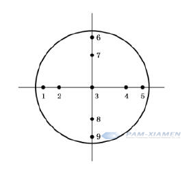
Fig. 1 Schematic Diagram of the Nine-Point Method Test Point Location for Germanium
Table 1 Test Point Position for Germanium Single Crystal (unit: mm)
| Diameter | Distance between test point and edge | Diameter | Distance between test point and edge | ||||||||
| 1,6 | 2,7 | 3 | 4,8 | 5,9 | 1,6 | 2,7 | 3 | 4,8 | 5,9 | ||
| 10 | 1.5 | 2.7 | 5 | 5.3 | 8.5 | 32 | 2.8 | 7.3 | 16 | 24.7 | 29.2 |
| 11 | 1.5 | 2.9 | 5.5 | 8.1 | 9.5 | 33 | 2.8 | 7.5 | 16.5 | 25.5 | 30.2 |
| 12 | 1.6 | 3.1 | 6 | 8.9 | 10.4 | 34 | 2.9 | 7.8 | 17,0 | 26.2 | 31.1 |
| 13 | 1.6 | 3.3 | 6.5 | 9.7 | 11.4 | 35 | 3 | 8 | 17.5 | 27,0 | 32,0 |
| 14 | 1.7 | 3.5 | 7 | 10.5 | 12.3 | 36 | 3 | 8.2 | 18 | 27.8 | 33 |
| 15 | 1.8 | 3.7 | 7.5 | 11,3 | 13.2 | 37 | 3.1 | 8.4 | 18.5 | 28.6 | 33.9 |
| 16 | 1.8 | 4 | 8 | 12,0 | 14,2 | 38 | 3.1 | 8.6 | 19 | 29.4 | 34 |
| 17 | 1.9 | 4.2 | 8.5 | 12.8 | 15.1 | 39 | 3.2 | 8.8 | 19.5 | 30.2 | 35.8 |
| 18 | 1.9 | 4.4 | 9 | 13,6 | 16.1 | 40 | 3.2 | 9 | 20 | 31,0 | 36.8 |
| 19 | 2 | 4.6 | 9.5 | 14,4 | 17 | 4 1 | 3.3 | 9.2 | 20.5 | 31.8 | 37,7 |
| 20 | 2.1 | 4.8 | 10 | 15.2 | 17.9 | 42 | 3.4 | 9.5 | 21 | 32.5 | 38.6 |
| 21 | 2.1 | 5 | 10.5 | 16 | 18.9 | 43 | 3.4 | 9.7 | 21.5 | 33.3 | 39.6 |
| 22 | 2.2 | 5.2 | 11 | 16,8 | 19.8 | 44 | 3.5 | 9.9 | 22,0 | 34.1 | 40.5 |
| 23 | 2.2 | 5.4 | 11.5 | 17,6 | 20.8 | 45 | 3.5 | 10.1 | 22,5 | 34,9 | 41.5 |
| 24 | 2.3 | 5.6 | 12 | 18.4 | 21.7 | 46 | 3.6 | 10.3 | 23 | 35.7 | 42.4 |
| 25 | 2.4 | 5.9 | 12.5 | 19.1 | 22.6 | 47 | 3.7 | 10.5 | 23.5 | 36.5 | 43.3 |
| 26 | 2.4 | 6.1 | 13 | 19,9 | 23.6 | 48 | 3.7 | 10.7 | 24 | 37.3 | 44.3 |
| 27 | 2.5 | 6,3 | 13,5 | 20,7 | 24,5 | 49 | 3.8 | 10,9 | 24,5 | 38,1 | 45,2 |
| 28 | 2.5 | 6.5 | 14 | 21.5 | 25.5 | 50 | 3.8 | 11.1 | 25 | 38.9 | 46.2 |
| 29 | 2.6 | 6.7 | 14.5 | 22.3 | 26.4 | 51 | 3.9 | 11.4 | 25.5 | 39.6 | 47.1 |
| 30 | 2.7 | 6.9 | 15 | 23.1 | 27.3 | 52 | 4 | 11.6 | 26 | 40.4 | 48 |
| 31 | 2.7 | 7.1 | 15.5 | 23.9 | 28.3 | 53 | 4 | 11.8 | 26.5 | 41.2 | 49 |
| 54 | 4.1 | 12 | 27 | 42 | 49.9 | 79 | 5.5 | 17.3 | .39.5 | 61.7 | 73.5 |
| 55 | 4.1 | 12,2 | 27,5 | 42.8 | 50.9 | 80 | 5,6 | 17,5 | 40 | 62,5 | 74,4 |
| 56 | 4.2 | 12.4 | 28 | 43.6 | 51.8 | 81 | 5.7 | 17.7 | 40.5 | 63.3 | 75.3 |
| 57 | 4.2 | 12.6 | 28.5 | 44.4 | 52.8 | 82 | 5.7 | 17.9 | 41 | 64.1 | 76.3 |
| 58 | 4.3 | 12.8 | 29 | 45.2 | 53.7 | 83 | 5.8 | 18.1 | 41.5 | 64.9 | 77.2 |
| 59 | 4.4 | 13 | 29.5 | 46,0 | 54.6 | 84 | 5.8 | 18.3 | 42,0 | 65,7 | 78.2 |
| 60 | 4.4 | 13.3 | 30 | 46.7 | 55.6 | 85 | 5.9 | 18.5 | 42.5 | 66.5 | 79.1 |
| 61 | 4.5 | 13.5 | 30.5 | 47.5 | 56.5 | 86 | 6 | 18.8 | 4.3.0 | 67.2 | 80 |
| 62 | 4.5 | 13.7 | 31 | 48.3 | 57,5 | 87 | 6 | 19 | 43.5 | 68,0 | 81 |
| 63 | 4, 6 | 13.9 | 31,5 | 49,1 | 58,4 | 88 | 6.1 | 19,2 | 44,0 | 68,8 | 81.9 |
| 64 | 4.7 | 14.1 | 320 | 49.9 | 59,3 | 89 | 6.1 | 19,4 | 44.5 | 69,6 | 82.9 |
| 65 | 4.7 | 14.3 | 32.5 | 50.7 | 60.3 | 9o | 6.2 | 19.6 | 45 | 70.4 | 83.8 |
| 66 | 4.8 | 14.5 | 33.O | 51.5 | 61.2 | 91 | 6.3 | 19.8 | 45.5 | 71.2 | 84.7 |
| 67 | 4.8 | 14,7 | 33.5 | 52,3 | 62,2 | 92 | 6.3 | 20,0 | 46,0 | 72,0 | 85,7 |
| 68 | 4.9 | 14.9 | 34 | 53.1 | 63.1 | 93 | 6.4 | 20.2 | 46,5 | 72.8 | 86.6 |
| 69 | 5 | 15.2 | 34.5 | 5.3.8 | 64 | 94 | 6.4 | 20.4 | 47 | 73.6 | 87.6 |
| 70 | 5 | 15.4 | .35,0 | 54.6 | 65 | 95 | 6.5 | 20.7 | 47.5 | 74.3 | 88.5 |
| 71 | 5.1 | 15.6 | 35,5 | 55,4 | 65,9 | 96 | 6.5 | 20.9 | 48,0 | 75,1 | 89,5 |
| 72 | 5.1 | 15,8 | 36 | 56,2 | 66,9 | 97 | 6.6 | 21.1 | 48,5 | 75,9 | 90,4 |
| 73 | 5.2 | 16 | 36.5 | 57,0 | 67.8 | 98 | 6.7 | 21.3 | 49 | 76.7 | 91.3 |
| 74 | 5.3 | 16.2 | 37,0 | 57,8 | 68.7 | 99 | 6.7 | 21,6 | 49,5 | 77,5 | 92,3 |
| 75 | 5.3 | 16,4 | 37,5 | 58.6 | 69,7 | 100 | 6.8 | 21,7 | 50 | 78,3 | 93,2 |
| 76 | 5.4 | 16.6 | 38 | 59.4 | 70.6 | 110 | 7.4 | 23.8 | 55,0 | 81.2 | 102,6 |
| 77 | 5.4 | 16.8 | 38.5 | 60.2 | 71.6 | 130 | 8.6 | 28 | 65 | 102,0 | 121.4 |
| 78 | 5.5 | 17.1 | 39 | 60.9 | 72.5 | 150 | 9.8 | 32.2 | 75 | 117.8 | 140.2 |
Mark: the diameter is germanium single crystal (or germanium single crystal internal cutting sample) diameter.
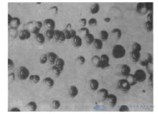
Fourthly, observe the selected test points with a metallurgical microscope, refer to the characteristics of dislocation corrosion pits on different crystal planes shown in Figure 2, read and record the number of dislocation corrosion pits at each test point;
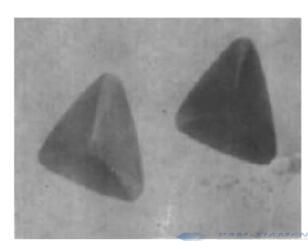
a {111} Crystal Plane Dislocation Corrosion Pit (Two-Step Method) 400 x
b {111} Crystal Plane Dislocation Corrosion Pit (One-Step Method) 160X
c {100} Crystal Plane Dislocation Corrosion Pit 200x
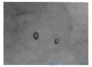
d {113} Crystal Plane Dislocation Corrosion Pit 250×
Fig. 2 Germanium Single Crystal Dislocation Etch Pit
Then, dislocation corrosion pits on the boundary of the field of view should be counted only if at least 1/2 of the area is in the field of view. When there are many dislocation corrosion pits and overlap, the dislocation corrosion pits of monocrystal germanium wafer are counted according to the number of pit bottoms that can be seen, the dislocation corrosion pits at the bottom of the pit are counted in the field of view, and the dislocation corrosion pits at the bottom of the pit are outside the field of view. Pits are not counted. Unqualified pits, flat-bottomed pits or other shapes are not counted. If there are many contamination points or other shapes with uncertain shapes in the field of view, re-sampling should be considered.
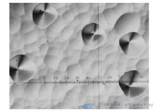
Lastly, during the dislocation density test for monocrystal germanium substrate, if small-angle grain boundaries (see Figure 3) and dislocation arrangements (see Figure 4) are observed, the length can be measured with a microscope or a vernier caliper. It should be noted in the test report.
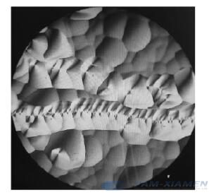
Fig.3 Small-Angle Grain Boundaries 200X of Monocrystal Germanium
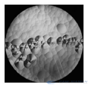
Fig.4 Dislocation Arrangements 200X of Germanium Sample
7. Processing of Test Data for Germanium
The dislocation density Nd is calculated according to formula (1):
Nd = n/S (1)
In formula:
“Nd” is the dislocation density; the unit is per square centimeter (cm-2);
“n” is the number of dislocation corrosion pits in the field of view;
“S” is the field of view area; the unit is square box meter (cm2).
Average dislocation density Nd. Calculate according to formula (2):
In formula:
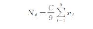 (2)
(2)
“Nd” is the average dislocation density; the unit is per square centimeter (cm-2);
“C” is the preset calculation coefficient of the microscope. C=S-1;
“ni” is the number of dislocation corrosion pits at the first test point. i=1.2.3……9
Find the maximum and minimum readings from the 9-point readings, and then multiply them by C to obtain the maximum dislocation density Nmax and the minimum dislocation density Nmin.
8. Precision of Germanium Dislocation Density Tested
The error of testing dislocation density using the principle of preferential corrosion is related to the selection method of test points, the ratio of the actual observation area (the area of the field of view multiplied by the number of test points) to the total area of the monocrystal germanium plane, and the uniformity of the dislocation distribution. The total average value of the three tests of the nine-point method and equal deflection angle is used as the true value of the dislocation density of the test piece. The average dislocation density of the random nine-point method is used as the single test value to obtain the single test of the dislocation density, calculating the relative error between the value and the actual value. The sum of the average value of the relative error and the standard deviation of 3 times the relative error is used as the test error within the range of the corresponding dislocation density.
In the dislocation density range of <500cm-2, 500~1000cm-2, >1000cm-2, respectively select 30 germanium single crystal test pieces with a diameter of 100mm~120mm, and test them in a single laboratory by the nine-point method. <1000cm-2, ≥1 000-2 dislocation density range, respectively select a piece of monocrystal germanium test piece with a diameter of 100mm. Test 20 times with the nine-point method in 4 laboratories, and the precision meets the requirements of Table 2. .
Table 2 Precision of Monocrystal Germanium Dislocation Density Tested
| Dislocation Density Range cm-2 | Relative Error | Test Error |
| <1000 | ≤30% | ≤70% |
| ≥1 000 | ≤20% | ≤40% |

For more information, please contact us email at victorchan@powerwaywafer.com and powerwaymaterial@gmail.com.